
Fire alarm systems are critical for building safety, and understanding how they are represented in diagrams is essential for engineers, designers, and technicians. Two commonly used types of diagrams in fire alarm system design are schematics and wiring diagrams. While they may appear similar at first glance, they serve distinct purposes and convey different levels of detail. XTEN-AV explores the differences between fire alarm schematics and wiring diagrams, their applications, and how Fire Alarm System Design Software can help create accurate representations.
Introduction to Fire Alarm Diagrams
Diagrams are essential tools in fire alarm system design. They provide a visual representation of components, connections, and overall system logic. Accurate diagrams help ensure proper installation, maintenance, troubleshooting, and compliance with fire safety codes such as NFPA 72.
Engineers and students working on fire alarm projects need to understand which type of diagram to use for a specific purpose. Fire alarm schematics focus on system functionality and logic, while wiring diagrams provide detailed instructions for connecting devices electrically.
Fire Alarm Schematic Diagram
A fire alarm schematic diagram, often referred to simply as a schematic, illustrates how the system operates. It focuses on the logical relationships between components rather than the physical layout. Schematics are essential during the design phase to ensure the system functions correctly and meets safety standards.
Key Features of a Fire Alarm Schematic
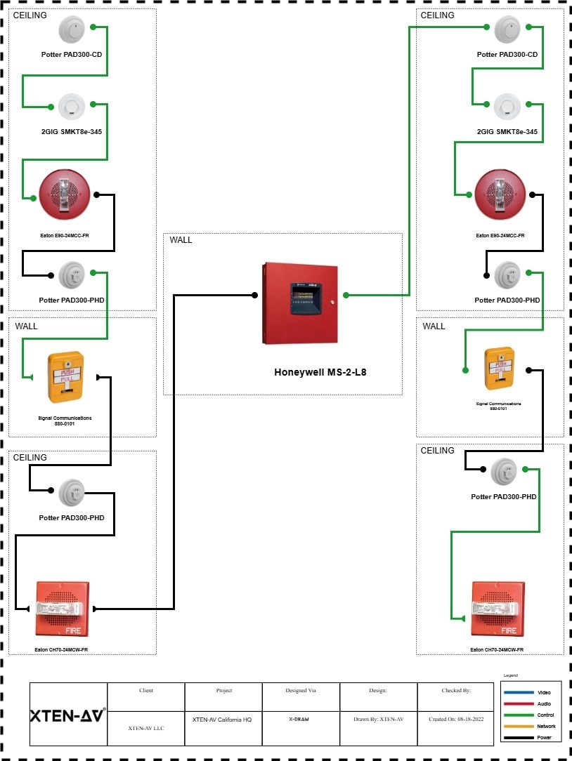
Logical Representation: Schematics show the relationship between devices, such as smoke detectors, heat detectors, control panels, notification appliances, and manual pull stations.
Component Symbols: Standard symbols are used to represent devices, ensuring clarity and consistency. Examples include circles for detectors, rectangles for control panels, and icons for horns or strobes.
System Functionality: Schematics highlight how signals flow through the system. For example, they show how a smoke detector triggers the control panel, which then activates notification devices.
Zoning and Loops: Schematics often include zones or loops to indicate areas monitored by specific devices. This helps designers plan system coverage and ensures proper response during an alarm event.
Advantages of Schematics
-
Simplifies understanding of system logic
-
Helps in design and planning stages
-
Facilitates troubleshooting by showing functional connections
Fire Alarm Wiring Diagram
A wiring diagram, sometimes called a connection diagram, focuses on the physical and electrical connections between devices. It provides the detailed instructions needed for installation, maintenance, and troubleshooting. Wiring diagrams are critical for electricians, installers, and technicians who must ensure that devices are correctly connected and powered.
Key Features of a Fire Alarm Wiring Diagram
Physical Layout: Wiring diagrams often represent the actual placement of devices and wiring paths. This helps installers understand where to run cables and how to connect devices.
Detailed Connections: Wiring diagrams provide specific details on wire types, colors, terminal points, and voltage requirements. This ensures proper installation and reliable system operation.
End-of-Line Devices: Wiring diagrams indicate supervision components such as resistors or relays, which monitor circuit integrity.
Power Distribution: Wiring diagrams show how primary and backup power supplies are connected to various devices, ensuring uninterrupted operation.
Advantages of Wiring Diagrams
-
Provides step-by-step guidance for installation
-
Ensures accurate electrical connections
-
Helps troubleshoot faults and circuit failures
Differences Between Schematics and Wiring Diagrams
While both schematics and wiring diagrams are essential for fire alarm system design, their purposes and details differ:
Focus: Schematics focus on system logic and functionality, while wiring diagrams focus on physical connections and electrical details.
Level of Detail: Schematics simplify representation using symbols and lines, omitting wiring specifics. Wiring diagrams provide detailed instructions for connecting each device.
Audience: Schematics are primarily used by designers, engineers, and planners. Wiring diagrams are intended for installers, electricians, and technicians.
Application: Schematics are useful during design, testing, and troubleshooting of system logic. Wiring diagrams are essential during installation and maintenance.
How Fire Alarm System Design Software Helps
Modern Fire Alarm System Design Software can generate both schematics and wiring diagrams, providing a complete solution for designers and technicians.
Automated Diagram Generation: Software can create schematics from device placement and logic, while simultaneously generating wiring diagrams with detailed connections.
Standardized Symbols: Built-in libraries ensure consistent use of symbols across schematics and wiring diagrams, reducing errors and improving readability.
Compliance Checks: Many platforms include code verification features to ensure that designs meet NFPA standards and local regulations.
Visualization and Documentation: 2D and 3D views help visualize device placement, coverage, and wiring paths. The software can also produce professional documentation for installation and maintenance teams.
Collaboration: Cloud-enabled platforms allow multiple team members to work on the same project, maintaining consistency between schematics and wiring diagrams.
Best Practices for Using Diagrams in Fire Alarm Design
-
Always create a schematic first to define system logic before working on wiring diagrams.
-
Use standardized symbols to ensure clarity and compliance.
-
Verify that wiring diagrams include all necessary details such as wire type, voltage, and end-of-line devices.
-
Cross-reference schematics and wiring diagrams to ensure that design intent aligns with physical installation.
-
Leverage software to automate diagram creation, reduce errors, and save time.
Conclusion
Understanding the difference between a fire alarm schematic and a wiring diagram is essential for designing, installing, and maintaining reliable fire alarm systems. Schematics provide a clear view of system logic, while wiring diagrams provide detailed instructions for physical connections.
XTEN-AV highlights that leveraging Fire Alarm System Design Software simplifies both types of diagrams, ensuring accuracy, compliance, and efficiency. By using these tools, designers and installers can work with confidence, creating systems that protect lives and property while streamlining the workflow from design to installation and maintenance.
