
Behind every modern car’s convenience feature lies a complex ecosystem of electronic modules. While most attention is given to the engine control unit or infotainment systems, the mini footwell module (FRM) quietly manages critical everyday functions such as lighting, windows, and mirror control. Though compact and hidden, it represents a sophisticated piece of electrical and software engineering, acting as both a distribution node and a communication gateway within the vehicle’s electronic architecture.
Strategic Role in Vehicle Architecture
Located in the driver’s footwell area, the FRM sits at the intersection of user inputs, electrical loads, and vehicle-wide communication networks. Its strategic role includes:
- Load Switching and Distribution – Managing high-current devices like headlights, fog lamps, and window motors.
- Signal Processing – Interpreting input from switches, sensors, and network messages.
- Diagnostics and Safety Monitoring – Detecting and reporting failures such as short circuits or bulb outages.
- Network Node Operation – Acting as a bridge between the CAN (Controller Area Network) and LIN (Local Interconnect Network) buses.
Its location provides accessibility to wiring harnesses that extend to the doors, dashboard, and front lighting, making it an efficient hub for local electrical control.
Hardware Engineering Inside the FRM
Designing the FRM involves integrating mechanical resilience with advanced electronics capable of handling demanding automotive environments.
Microcontroller Core
The embedded microcontroller executes all logic and communication tasks. Automotive-grade controllers are selected for their:
- Real-time responsiveness, handling lighting commands in milliseconds.
- Low-power modes, ensuring battery preservation when the car is idle.
- Robust peripheral integration, such as CAN controllers and analog-to-digital converters.
Power and Protection Circuits
The automotive electrical system is notorious for noise and voltage instability. The FRM integrates:
- Transient suppression to absorb load dumps during alternator disconnection.
- Reverse polarity protection for safety during battery mishandling.
- Current sensors that provide feedback for load monitoring.
Output Drivers
Lighting and motor systems demand high-current switching. The FRM’s MOSFET drivers provide:
- Thermal shutdown protection.
- Open-load detection (alerting the driver to a failed bulb).
- Pulse-width modulation (PWM) dimming control for interior lighting.
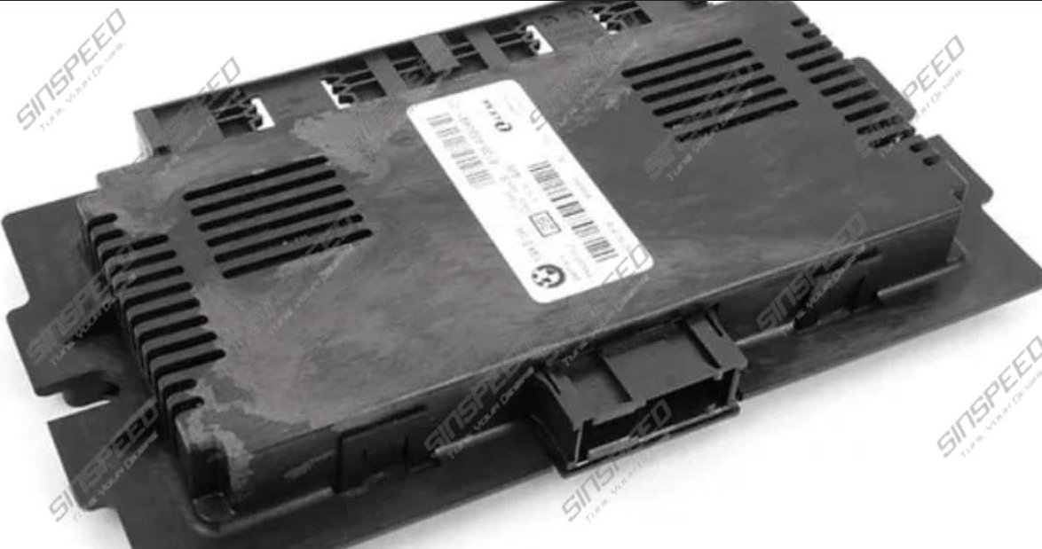
Mechanical Housing
Durability is achieved through:
- Vibration-resistant PCB mounting.
- Moisture-resistant enclosures.
- Conformal coatings to guard against dust and condensation typical in the footwell.
Embedded Software: The Intelligence of Control
The FRM’s software defines its functional sophistication. Engineers employ layered architectures that include:
- Input Processing – Switch signals are filtered to avoid false triggers caused by contact bounce.
- Control Logic – Rules like “windows deactivate above a set vehicle speed” or “lights turn off after ignition off” are programmed.
- Diagnostics and Logging – Fault codes are generated and transmitted for service diagnostics.
- Fail-Safe Behavior – Ensures critical functions such as hazard lights remain operational even under partial failures.
Software updates can also enhance functionality over a product’s lifecycle, aligning the FRM with evolving vehicle systems.
Functional Safety Considerations
Because the FRM handles systems directly tied to visibility and signaling, its design must align with ISO 26262 functional safety standards. Key principles include:
- Hazard Analysis – Identifying risks such as total lighting failure.
- Redundancy – Designing fallback mechanisms to ensure minimum safe lighting.
- Safe State Defaults – For example, headlights defaulting on if the module loses communication with the network.
- Continuous Self-Checks – Monitoring memory integrity, driver circuit health, and communication line integrity.
These practices ensure that even in the presence of hardware or software faults, driver safety is not compromised.
Integration with Vehicle Networks
Modern vehicles are networked systems of dozens of ECUs. The FRM communicates with:
- Body Control Module (BCM): Synchronizing door locks, alarms, and central lighting strategies.
- Engine Control Module (ECM): Adjusting electrical loads during cranking or low-voltage conditions.
- Instrument Cluster: Reporting status and fault codes to alert the driver.
- Door Control Units: Managing local functions such as mirror folding or window control.
The FRM’s dual-bus capability allows it to manage both high-speed CAN communication and low-cost LIN devices. This reduces wiring complexity while maintaining system flexibility.
Engineering Challenges
Designing the FRM involves overcoming a series of technical challenges:
- Thermal Management: High-current drivers for motors and lamps generate heat, requiring careful PCB layout and thermal design.
- Moisture Resistance: Its footwell location makes it vulnerable to water ingress from leaks.
- Electromagnetic Compatibility (EMC): The FRM must operate in noisy environments without causing or suffering from interference.
- Lifecycle Durability: It must endure years of switching cycles for windows and lamps without degradation.
Testing regimes simulate these stresses to validate design robustness before deployment.
Evolution Across Generations
The mini footwell module has evolved alongside vehicle electronics:
- First Generation: Relays replaced by electronic switches for improved reliability.
- Second Generation: CAN communication enabled advanced diagnostics and smarter control.
- Modern Units: Support for adaptive lighting, energy-efficient load balancing, and programmable software updates.
This progression reflects the industry-wide move toward more integrated, software-defined architectures.
Testing and Validation Protocols
Engineering validation of the FRM involves:
- Thermal Cycling: Exposing the module to repeated hot and cold extremes.
- Vibration Testing: Simulating the road-induced stresses endured over years.
- Salt Spray and Humidity Exposure: Checking for corrosion resistance.
- Electrical Stress Testing: Applying surges and transients to ensure survival of real-world voltage events.
- EMC Testing: Ensuring compliance with international automotive standards.
Only after passing these exhaustive tests can a module enter mass production.
Conclusion
The mini footwell module is far more than a switch box—it is a sophisticated control system that combines electrical robustness, embedded intelligence, and functional safety. By managing load distribution, interpreting driver inputs, and ensuring safe operation under extreme conditions, it represents a cornerstone of automotive body electronics.
Though hidden beneath trim panels, its engineering reflects the intersection of durability, precision, and reliability. And when challenges do arise with its performance, it is best to find a specialist near you who understands the interplay of hardware, software, and network dynamics within the FRM.
As vehicles continue to evolve toward electrification and autonomous systems, the FRM will remain a critical enabler of driver comfort and safety, exemplifying the hidden engineering complexity behind everyday convenience.
